


RTm-100 Series导通电阻测试装置在线可靠性测试评估系统 |
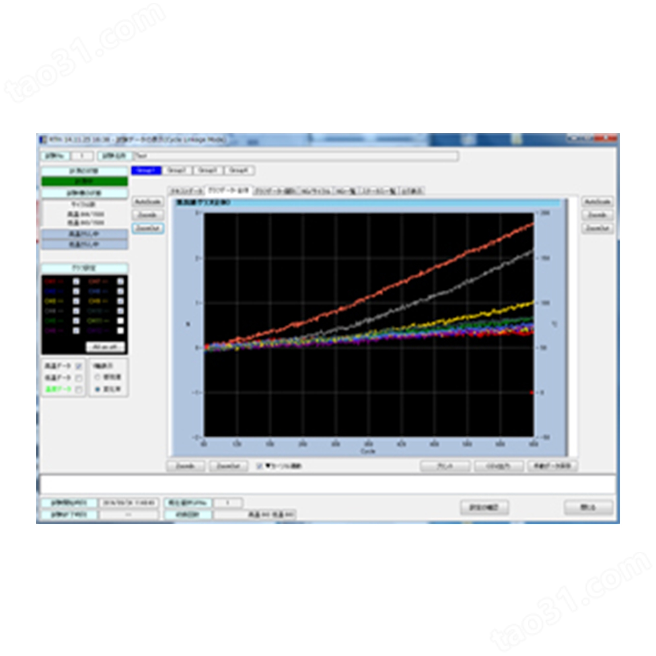
RTm-100 series of measurement circuit will capture the exact changes in the conduction resistance of less than a millimeter Ω. In conjunction with the thermal shock chamber, it is available data measured in conjunction to the temperature cycle. High-precision analog measurement circuit is also possible to the detection of small changes from the test cycle early. In addition, the high-speed scan function of the semiconductor relay, also fully follow the short test cycle time, nor does it shifts the timing of measurement for each cycle.
All of the measurement process is completed in Max240CH even less than 20 seconds. Even in a short cycle test of the cycle, the high-temperature side, at a low temperature side of the state, this system performs the measurement of the conduction resistance of all samples at the timing of the setting as expected.
It is capable of measuring a small resistance value of mΩ level by optimizing the special design of the measuring circuit and layout.
■Circuit block diagram
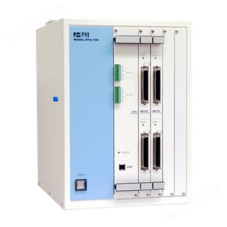
Case | RTm-100/96-n (n : Channel) | RTm-100/240-n (n : Channel) | |
Case type | 96CH type(maximum is 4 measurement unit) | 240CH type (maximum is 10 measurement unit) | |
Dimensions | 265W×330.3D×405H (protrusion is excluded) | 417.4W×330.3D×405H (protrusion is excluded) | |
Power consumption | About 20VA (when mount 4 measurement unit) | About 30VA (when mount 10 measurement unit) | |
Weight | About 15kg (when mount 4 measurement unit) | About 20kg (when mount 10 measurement unit) | |
Use power supply | AC100V 50/60Hz (can use it in other power supply area by UPS) | ||
Item | Specification/ performance/ others | ||||
Meas. Range | Impression current (AC) | Impression current (DC) | |||
200kΩ | 10Ω | @25uA | |||
20kΩ | 1Ω | @25uA | |||
2kΩ | 0.1Ω | @25uA | 0.1Ω | @250uA | |
200Ω | 10mΩ | @25uA | 10mΩ | @2.5mA | |
20 Ω | 1mΩ | @250uA | 1mΩ | @25mA | |
2Ω | 0.1mΩ | @2.5mA | 0.1mΩ | @25mA | |
200mΩ | 10μΩ | @25mA | |||
20mΩ | 1μΩ | @25mA | |||
Impression current | 16Bit resolution AD converter Range ±0.4% of FS. <200mΩ±1% of FS. | ||||
Impressed voltage | 16Bit resolution AD converter. Range ±0.4% of FS <200mΩ±1% of FS. | ||||
Current output ON/OFF | Current impression is automatically stopped as NG by the resistance detection. (This function can also be turned off) | ||||
Digital Input | Contact input×4 (be able to detect High/Low temp stage and count cycle number, Trigger Start/Stop) | ||||
Thermo couple input (Option) | A thermo couple is connected and temperature is measured. (Pt100/T) | ||||
Four-Terminal Cable | Length: 2m (joint cable) + 1.5m (Teflon, twisted pair) | ||||
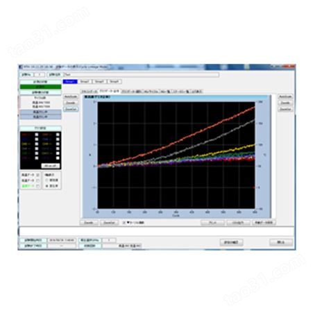
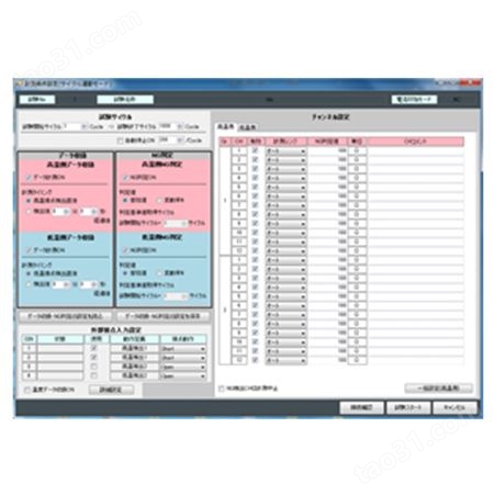
■Software
Item | Remarks | |
Test mode | Cycle link mode(Max 9999 cycles) | Interval record mode (set vale:1 minute~) |
Data record interval | 2 data per each cycle (High Temp and Low Temp) | 1data per Interval (50msec or less at fastest mode) |
Display function | Graph (X axis:cycles) NG plot (X axis:cycles) Meas. status per CH Temp. data (with Thermo Couple option) | Graph (X axis:Time) NG plot (X axis:Time) Meas. status per CH Temp. data (with Thermo Couple option) |
File output function | CSV file(High temperature data, the low-temperature data is separated output in a separate column) | |
Print function | Screen print | |
Hardware control | Start of test / end (12CH unit) measurement range change Impression current ON/OFF (NG judging value detection) | |
Noise rejection | Averaging (2.5 kSPS/20msec) | |
Scanning speed | 50msec/CH | |
导通电阻测试装置在线可靠性测试评估系统
所有评论仅代表网友意见,与本站立场无关。